InstanceGraph#
The InstanceGraph is instant3Dhub’s core concept to structure the data based on resources inside a 3D session. It reflects the data on a resource level as well as their internal structure for assembly resources. After adding a first resource, we will now take a look, how resources are assembled in webvis.
This tutorial will explain the InstanceGraph concept which is the central structure for many of webvis API functions.
The InstanceGraph is a hierarchical tree structure, which combines two major aspects, i.e. the logical representation of a scene graph and the semantic structure of CAD data like BOMs or assembly structures combined with the sub-assembly structures of the individual part structures.
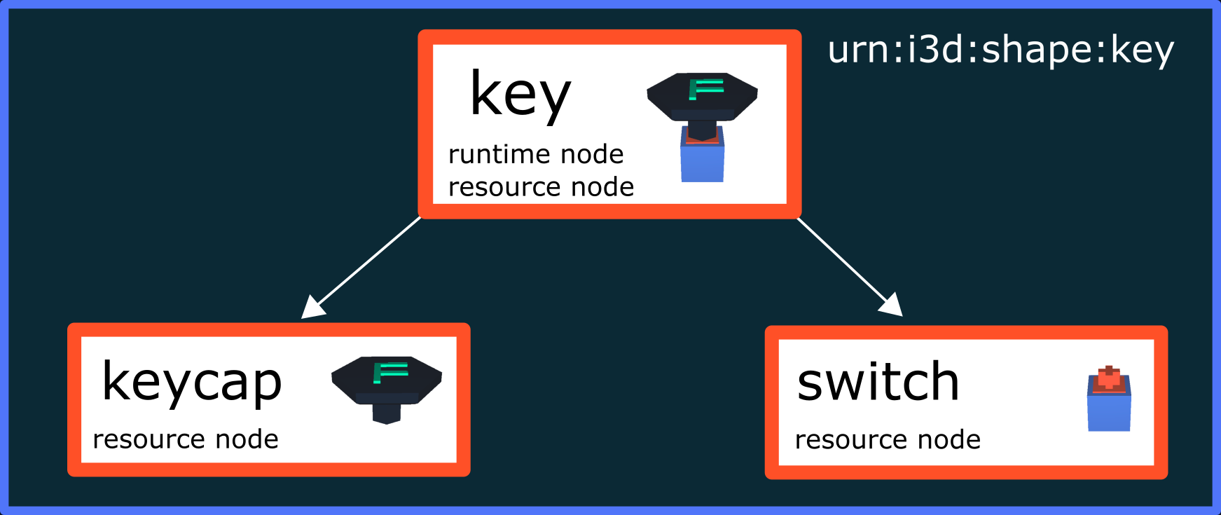
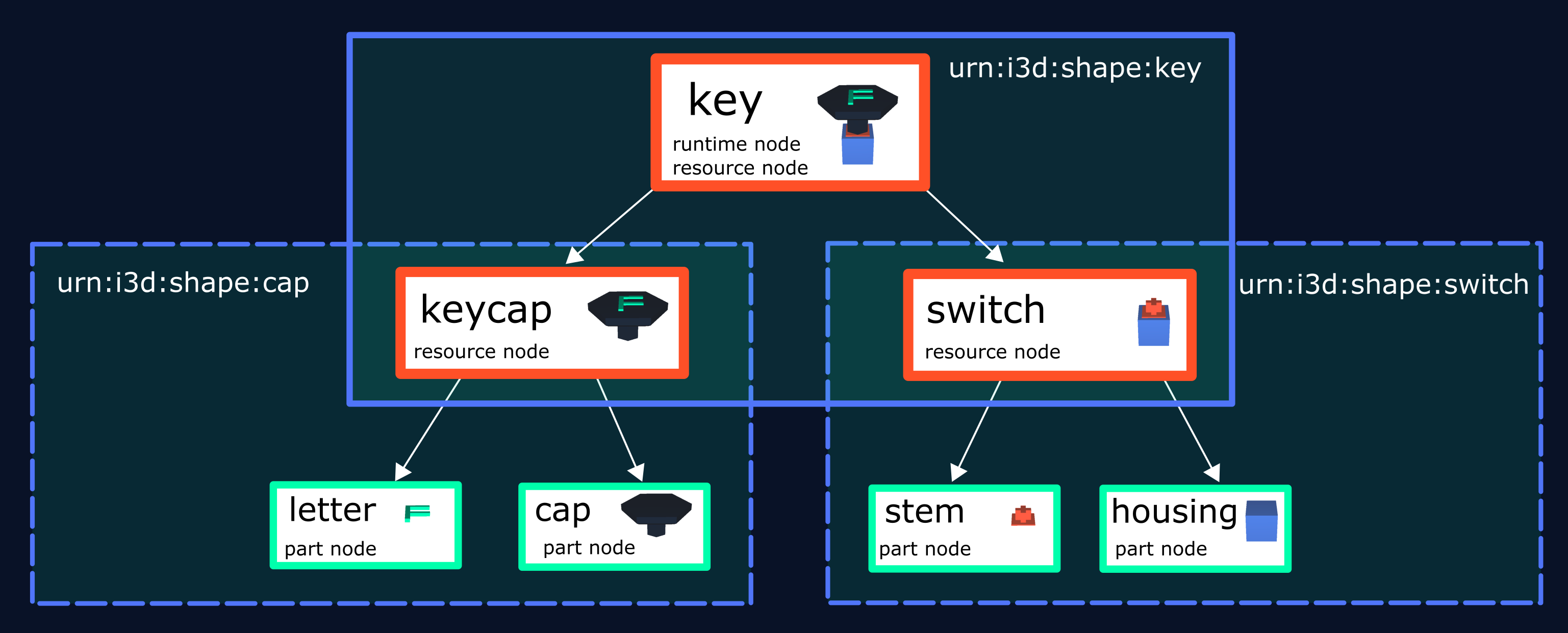
We illustrate the InstanceGraph using an example consisting of three different 3D CAD resources. The first resource is urn:x-i3d:shape:key, which is the assembly structure of a keyboard key. It has no geometry and references the CAD parts urn:x-i3d:shape:cap and urn:x-i3d:shape:switch which contain the actual CAD geometry:
assembly structure |
part structure |
part structure |
|---|---|---|
urn:x-i3d:shape:key |
urn:x-i3d:shape:cap |
urn:x-i3d:shape:switch |
|
|
|
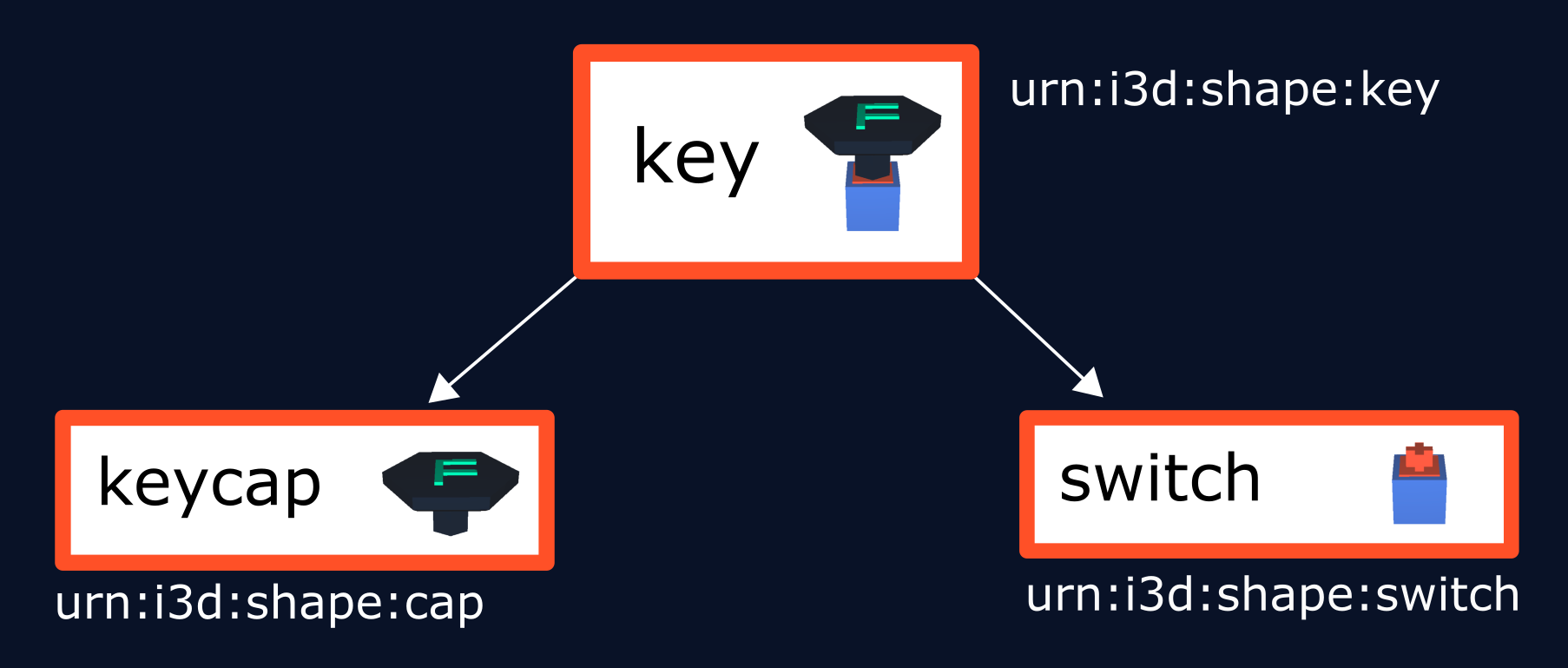
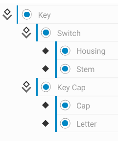
These resources form the following structure:
Scene Graph aspect#
All nodes are presented in a tree structure. This allows a clear and understandable presentation. Operations are applied to parts of the hierarchy. In the process these operations are applied along paths in graph. E.g. if a node is disabled, all nodes below it are also disabled.
CAD aspect#
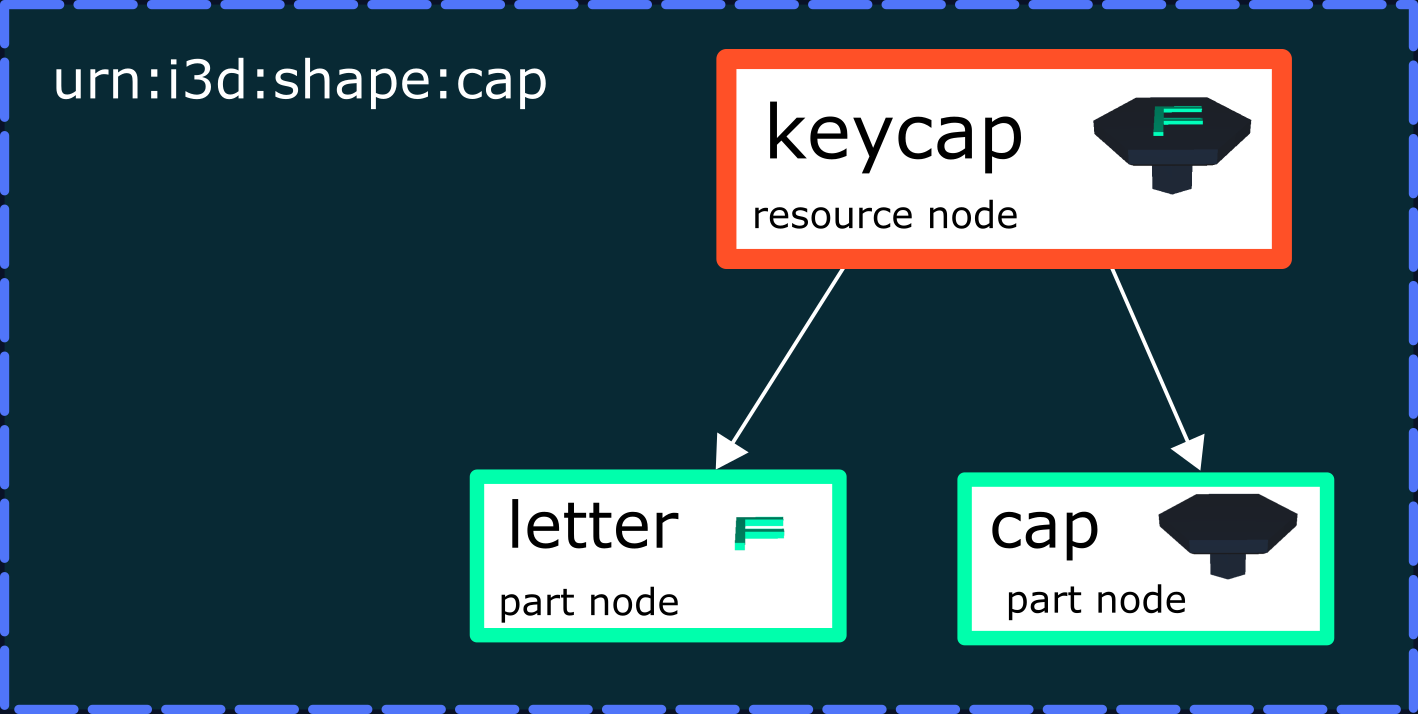
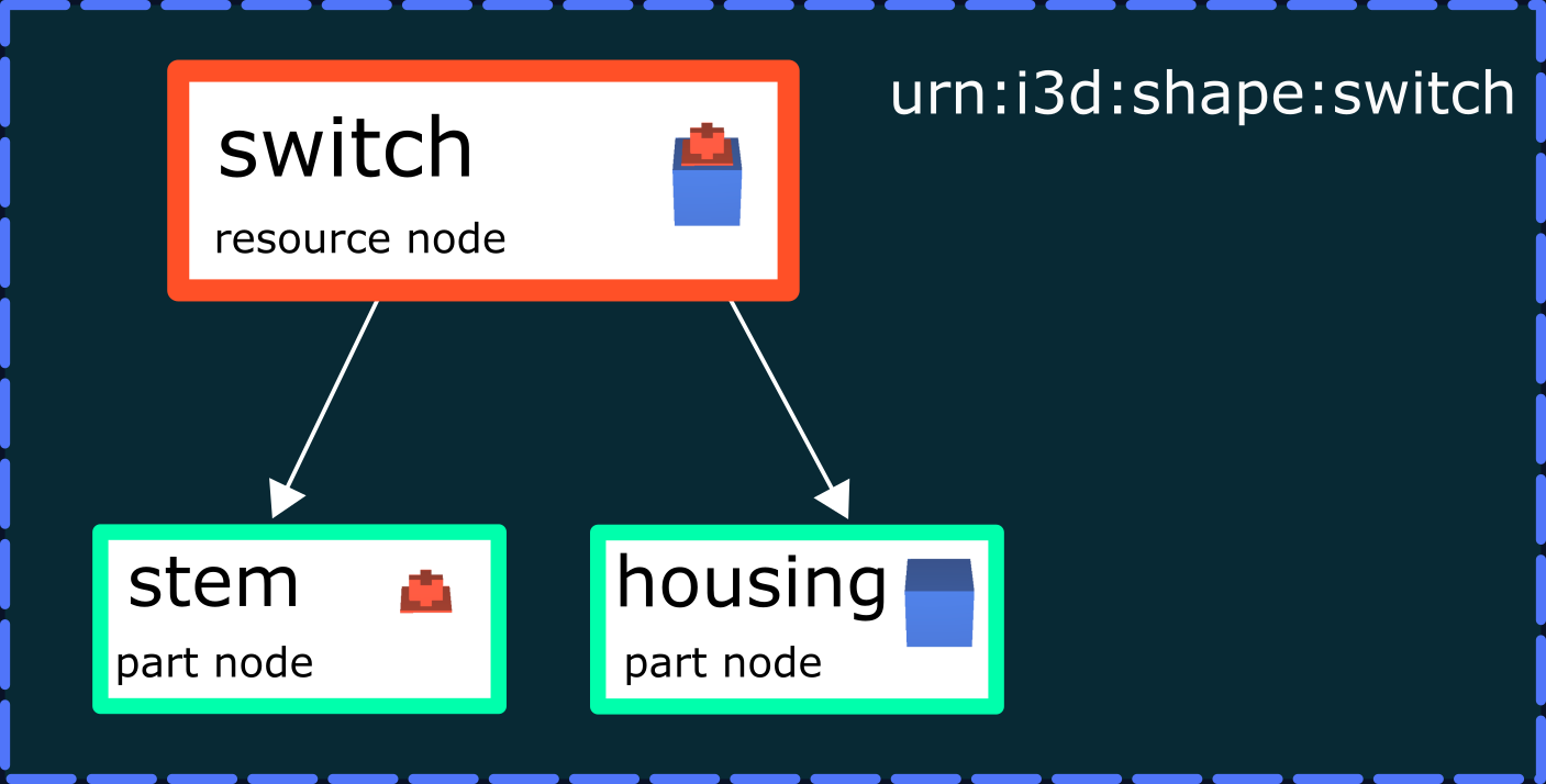
Constructions consist of multiple parts, where each part usually corresponds to a single CAD resource. These parts are assembled by references/links in a so called assembly structure, defined through structure files (e.g. PLMXML, step242, x3d). In our example, the CAD resource urn:x-i3d:shape:key defines an assembly structure, which links the two other CAD resources, urn:x-i3d:shape:cap and urn:x-i3d:shape:switch. Especially, larger parts usually have their own sub-assembly structure as e.g. keycap is subdivided into letter and cap.
The sub-assembly structure is then inserted into the assembly structure, which results into the InstanceGraph structure.
InstanceGraph#
The InstanceGraph is the composition of all assembly structures and sub-assembly structures of the corresponding linked CAD parts. Therefore, the nodes keycap and switch function as transitions to 3D resources.
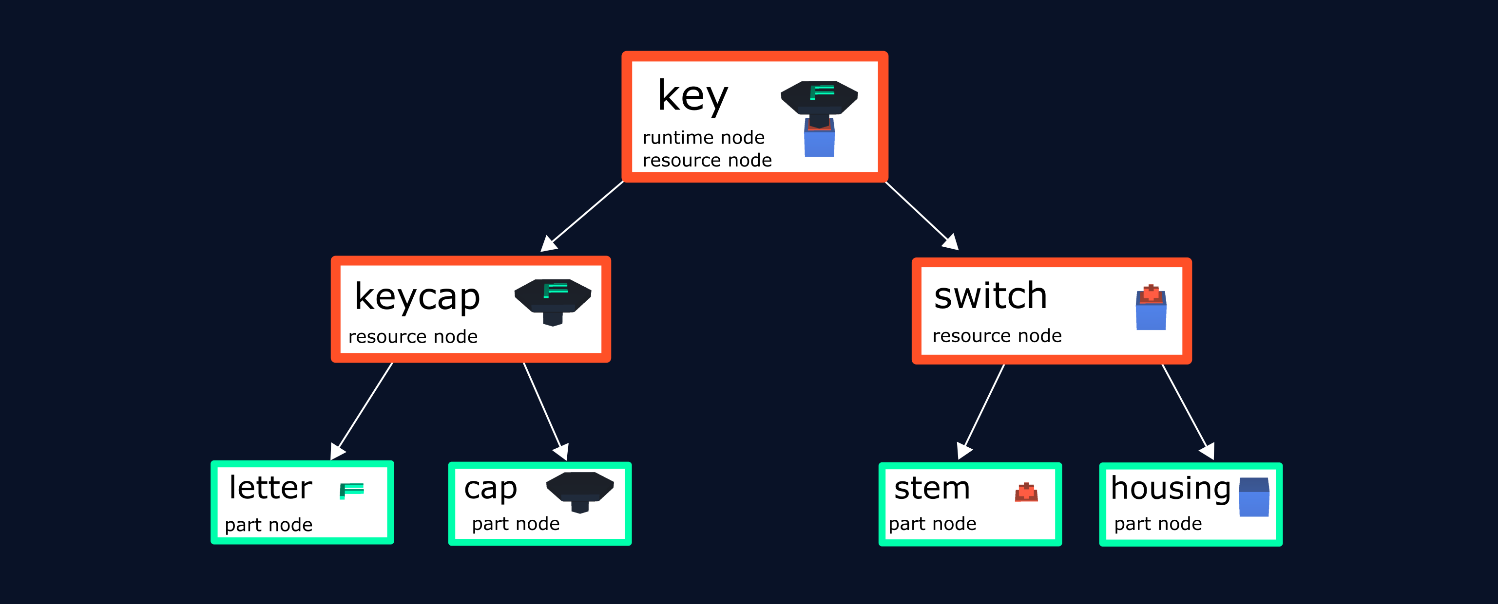
webvis creates a node for every part of the tree shown above.
Node Types#
There are different types of nodes, where as one node can also belong to multiple node types.
Part Nodes These nodes contain only the geometry itself.
Resource Nodes webvis uses resource nodes to build a bridge between geometry and the overall structure of a model. They contain no actual geometry.
Runtime Nodes As their name indicates runtime nodes are added during runtime. Every node added through the API is a runtime node. In our example “key” is a runtime node as it’s been loaded dynamically during runtime. Structures like switch or letter are no runtime nodes, because they are loaded through the key itself.
Warning
Key is also a resource node as it contains a link to other resource nodes.
InstanceGraph operations#
part node |
resource node |
runtime node |
|
|---|---|---|---|
color / transparency |
✔ |
✔ |
✔ |
transformation |
✖ |
✔ |
✔ |
enable / disable |
✔ |
✔ |
✔ |
pickable |
✔ |
✔ |
✔ |
remove |
✖ |
✔ |
✔ |
add |
✖ |
✖ |
✔ |
Some operations can’t be applied to certain types of nodes. The table above shows, what is allowed or not.